Modbus
 From
the Wiki,
Modbus is
a data communications protocol originally
published by Modicon (now Schneider Electric)
in 1979 for use with its programmable logic
controllers (PLCs).
Modbus has become a de facto standard communication
protocol and is now a commonly available means of connecting industrial electronic devices.
In short, Modbus is a request-response protocol where the client sends a
request to a device, and the device sends a response back to the client.
These are just 4 types Modbus protocols:
Modbus ASCII - a serial ASCII protocol
Modbus RTU - an 8 bit serial protocol
Modus TCP - a TCP/IP protocol
Modbus RTU/TCP - TCP/IP protocol w/CRC check
This page will deal mainly with Modbus RTU simply because this is
the stuff I have laying around on the bench.
Modbus Frame Formats

RS232 vs. RS485
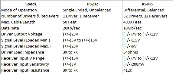
Both RS232 and RS485 are standard communication protocols and work with
Modbus. RS422 will also work but over the years it has lost it
popularity. Data is exchanged between sets of data line drivers
and receivers. RS232, the oldest of the Modbus protocols, is
unbalanced, single ended, and usually uses parallel wiring.
Because of this, transmission using RS232 tends to be slower (20Kb/sec)
and is limited in distances of 50 feet. On the other hand, RS485
is both balanced (120 ohms) and uses differential mode allowing for
transmission speeds of up to 10Mb/sec. and distances of up to 4000 feet.
It also uses twisted pair cables to prevent electrical noise, in addition
to line drivers which resolves ground level differences and impedance
mismatches. Modbus RTU (Remote Terminal Unit) uses RS485 for this
reason. The chart below details the differences between the two
standards.

Modbus RTU Format
Slave ID
The first byte in the string is the slave address, or device address.
Each device in the network is assigned a unique address from 1 to 247.
However, Modbus TCP/IP (Ethernet) with allow for greater device addresses.
Function Code or Protocol Data Unit (PDU)
The next byte in the data string is the Function Code, or Protocol Data
Unit. It tells the device how to respond.
-
0x01 (01)
- Read from table Discrete
Output Coils
-
0x02 (02)
- Read from table Discrete
Input Contacts
-
0x03 (03)
- Read from table Analog
Output Holding Registers
-
0x04 (04)
- Read from table Analog
Input Registers
-
0x05 (05)
- Write once to table Discrete
Output Coil
-
0x06 (06)
- Write once to table Analog
Output Holding Register
-
0x07 (07)
- Diagnostics - Read Exception Status
-
0x08 (08)
- Diagnostic
-
0x0B (11)
- Diagnostic - Get Com Event Counter
-
0x0C (12)
- Diagnostic - Get Com Event Log
-
0x0F (15)
- Write multiple times to table Discrete
Output Coils
-
0x10 (16)
- Write multiple times to table Analog
Output Holding Registers
-
0x11 (17)
- Diagnostics - Report Slave ID
-
0x14 (20)
- File Record Access - Read File Record
-
0x15 (21)
- File Record Access - Write File Record
-
0x16 (22)
- Mask Write Register in table Analog
Output Holding Registers
-
0x17 (23)
- Read/write multiple times to table Analog
Output Holding Registers
-
0x18 (24)
- Read FIFO Queue in table Analog
Output Holding Registers
-
0x2B (43)
- Diagnostics - Read Device Identification
Address
The next two bytes are the device output address, different from the Slave
ID.
Data
The next 2 bytes is the command (1 byte), followed by a delay (1 byte).
CRC (Cyclic Redundancy Check)
The last 2 bytes are for the CRC checksum value.
CRC Algorithm (in C#)
QModMaster
QModMaster is a free Qt based implementation of a Modbus master application.
It has a source code and libraries which allows the programmer to develop
Modbus interfaces. Qt is a
free open source Integrated Development Environment (IDE) which allows users
to develop software in multiple languages (C++, C#, Python, Javascript,
etc.) which could be compiled in multiple platforms (Windows, Linux, macOS,
Android, etc.). Programmers can convert seamlessly between operating
systems without changing source code.
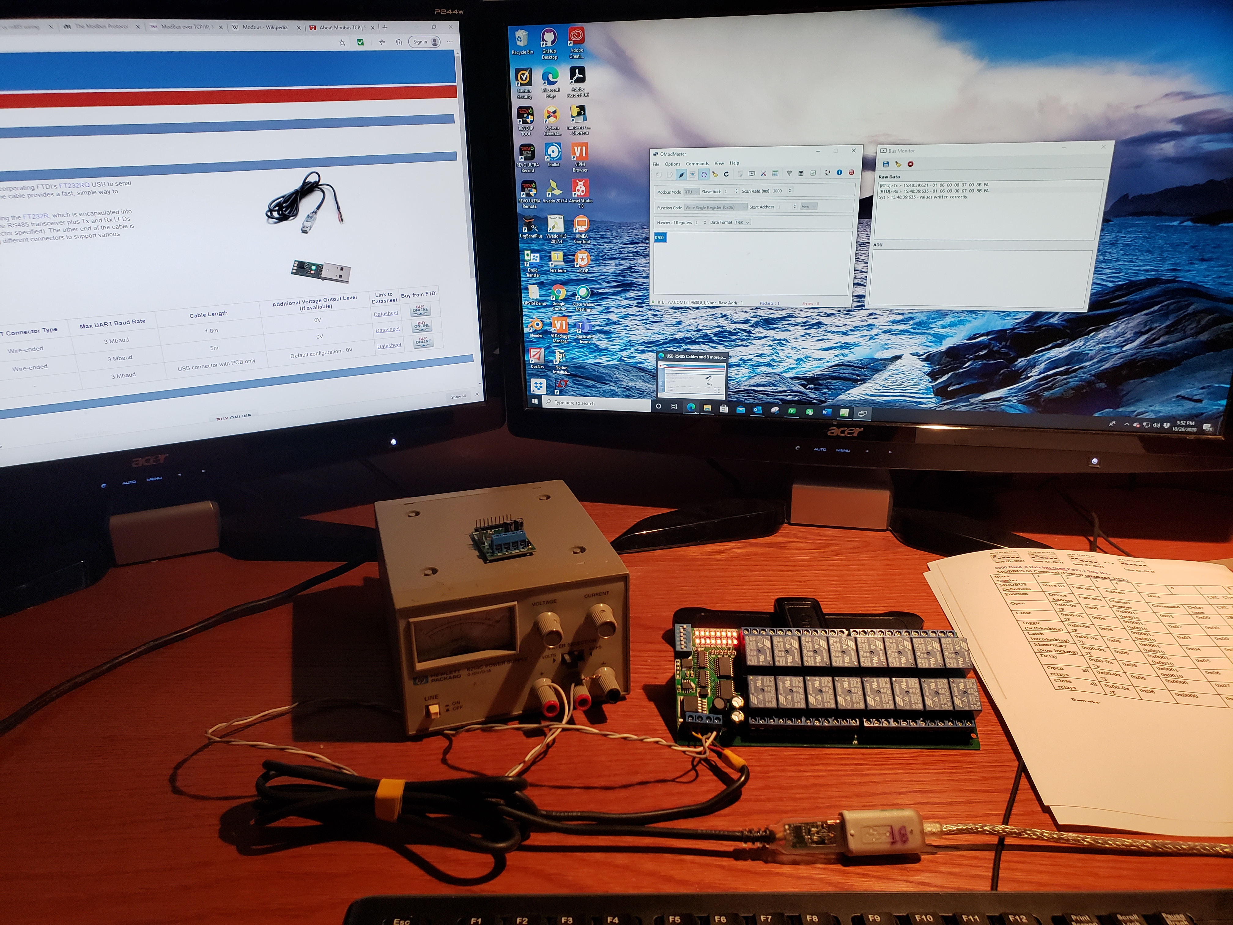
Below is a simple demonstration of Modbus RTU developed using Qt and
qModMaster. I went with Modbus RTU because the converters and devices
are cheaper than Modbus TCP/IP stuff. I am using a virtual comport
using a serial UART converter based off of FTDI's chip set
FT232R. It converts the USB port to RS485 needed for Modbus.
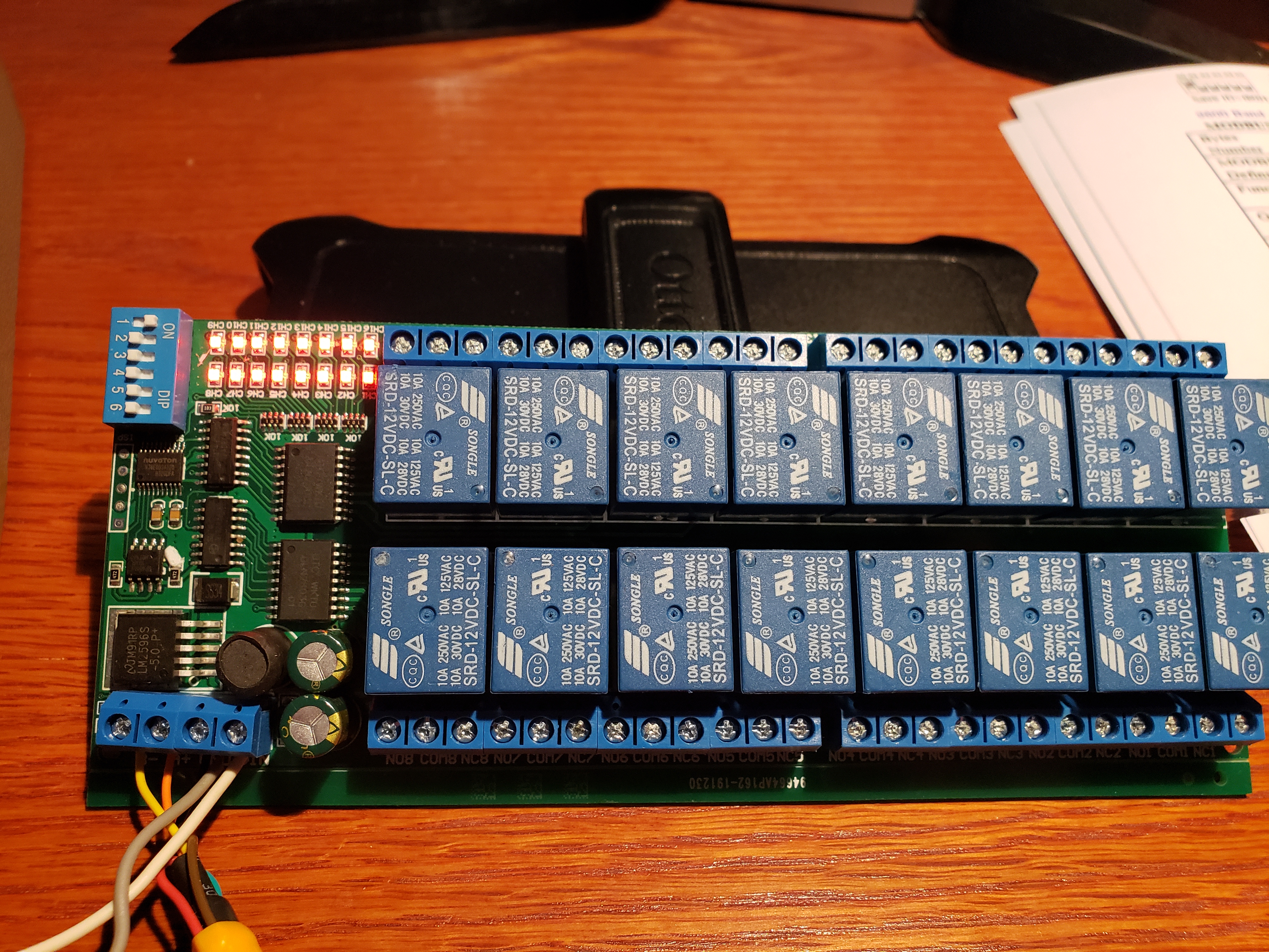
The device, or slave, is a R421B16 (16 Channel RS485 Relay board). It
uses a standard 3 wire Modbus connection (A+, B-, Ground), with an external 12V
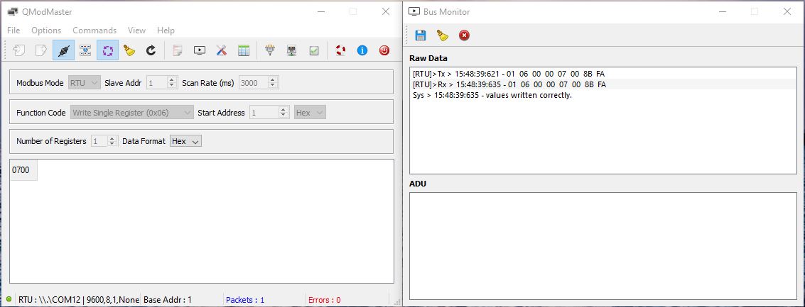
supply. A simple test, establish a connection using the virtual comm
port (COM12), and send a string to open all the relays. When I get 10
minutes I'll write a program to sequence the output ports.
Just a note, download the code and build the utility yourself. There
appears to be an error with the pre-built which was online, or at least the
version I was using.


Source:
The Modbus Protocol In-Depth (National Instruments)