Floating Neutral or
Ground-Neutral Voltage
A major source of measurement error is coming right from the Wall
Outlet. Differential Mode Noise or Floating Neutral Voltages are when the
Common and the Ground are not at the same potential. In an ideal case, the
Ground and the Common would measure zero volts right at the outlet. The
reality, in most large buildings it is far from it. By code, the Ground and
the Common cannot be tied together at the outlet. Instead they are tied
together at the main electrical panel which could be several hundred feet
away. This allows the Neutral to develop a voltage relative to the Ground.
But why should this be if the Ground and the Neutral are the same length?
The simple answer, electrically they're not. A Ground is the combination of
the wire conductor, the BX casing, the EMT conduit, the Earth, etc. making
the Ground less resistive than the Neutral. The differential of resistances
between Ground and Neutral is what induces the Ground-Neutral Voltage.
So how bad could it be? It depends on what you were doing. If you were to
have a Ground-Neutral Voltage above 1.0 VAC your communications adapter
(USB, GPIB, Ethernet, etc.) might hang up not knowing what logic zero was.
If you were talking current measurements you'd probably see an offset, or
currents that were bouncing around, and/or noise. Most measurement
equipment vendor recommend not using the equipment with Ground-Neutral
Voltages above 1.0 VAC. In some cases you could void your equipment
warrantees. In addition, most calibration services certify the equipment to
be used within a certain Ground-Neutral range, most being below 1.0 VAC.
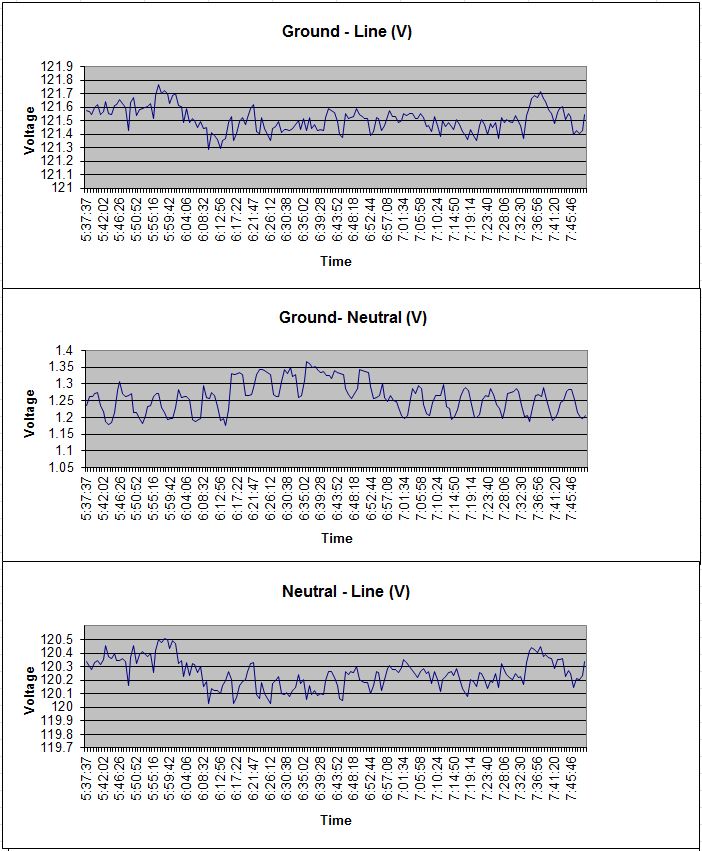
Below are some graphs of an outlet in my work area. This outlet is shared
with a air compressor I use for air tools. If you were looking at the
Ground to Line voltages you wouldn't know anything was wrong. But a closer
look at the Ground to Neutral voltage shows it is elevated about 1.0 VAC.
In addition, you can see something riding on the line AC. So as an
experiment I set up a simple circuit consisting of a 555 timer, a couple of
gates, and a LED to see what would happen if this output was used to power
an analog/digital circuit. Using clean power the LED flashed on-and-off as
the circuit was designed to do. Using the outlet with the elevated
Ground-Neutral the LED never turned off, the voltage at the LED was sitting
on an 0.8V offset.
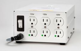
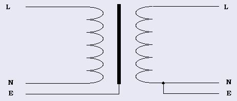
The good news, there's a fix. An Isolation Transformer ties the Ground and
the Neutral together at its secondary. This has several benefits; one is to
electrically isolate itself from the building Ground which could be noisy,
it also reduces the Ground-Neutral voltages because they're essentially tied
together at the secondary rather than at the building's electrical panel,
and depending on which type of Isolation Transformer you get Common-Mode
Noise would be reduced. These transformers are basically just a 1:1
windings with an extra dielectric barrier and an electrostatic shield
between primary and secondary. The grounded shield prevents capacitive
coupling between primary and secondary windings which helps eliminate
Common-Mode Noise. When I get a minute I'll go into what Common-Mode Noise
is all about. Please take note, not all Isolation Transformers are wired
the same. Some actually tie the Earth-Ground from the primary and the
secondary together. Please be sure you know what you are buying and what
your needs are.
Aside from measurement accuracy there are several other reasons why you
would want to use Isolation Transformers. One would be to protect users
from faulty equipment. Could you imagine being hooked up to electrodes in
the hospital being directly tied to building Ground?!?! Ground looping
is another which will be covered in the next article.