Electromagnetic Interference (EMI)
part 1
 So, here is the plan, you’re going to take your device/circuit/product and perform EMI testing.
It sounds simple enough. So you bias it up and measure either what's coming
in or going out. But is it really that simple?
So, here is the plan, you’re going to take your device/circuit/product and perform EMI testing.
It sounds simple enough. So you bias it up and measure either what's coming
in or going out. But is it really that simple?
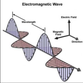
Before we do anything, we would need to know what Electromagnetic Interference and Electromagnetic Compatibility are.
From the Wiki, “Electromagnetic Interference (EMI), also called
Radio-Frequency Interference (RFI) when in the radio frequency spectrum, is a disturbance generated by an external source that affects an electrical circuit by electromagnetic induction, electrostatic coupling, or conduction”.
Also from the Wiki, “Electromagnetic Compatibility (EMC) is the ability of electrical equipment and systems to function acceptably in their electromagnetic environment, by limiting the unintentional generation, propagation and reception of electromagnetic energy which may cause unwanted effects such as electromagnetic interference (EMI) or even physical damage in operational equipment and electromagnetic compatibility (EMC)”.
Suddenly it stopped being simple.
I’ll try to simplify. EMI is an electromagnetic disruption coming from
either an external source, or being generated from within, which affects the
operation and performance of your circuit or device. EMI
characterization could be the measurement of signal(s) being generated from
your circuit or device, or signal(s) coming into your circuit or device.
It depends on what you are trying to prove. EMI can be one signal
narrowband sinusoidal signal, a broad spectrum pulse, or combinations of
several sources. The short of it is, EMI is anything but simple.
Sources of EMI
Man-Made EMI: is defined as interference generated by electrical circuits or devices but is not limited to.
Examples of man-made EMI sources would include power supplies, controllers, motors, servos,
actuators, transmitters, oscillators, generators, and engines.
Circuits or devices which use or switch large currents, or have large variations in voltage, could be classified as mam-made EMI.
Naturally Occurring EMI: examples of naturally occurring EMI would be lightning, cosmic noise, electro-static discharge (ESD), sun bursts, or
other environmental discharges of energy.
Inherent (or Internal) EMI: this often-forgotten interference is the noise produced inside a piece of equipment due to the agitation of electrons flowing through resistance materials.
Here we would have the circuit or device interfering with itself. Receiver
noise, referring to the background noise heard on radio receivers, is
Inherent EMI.
Types of EMI
Continuous Interference: is just what is sounds like, continuous interference signals or noise radiating from a
circuit, or device. Sources of this type of interference may include circuits containing oscillators,
electrical power line Hertz hum (60Hz US, 400Hz airborne, etc.), and ground
looping to name a few.
Impulse Interference: is caused by periodic pulses of
radiant energy produced by circuit or device like lightning, and switching systems,
or from electro-static discharge (ESD).
Bandwidth of EMI
Narrowband Interference: is usually sinusoidal and most
likely from a single carrier source like an oscillator, crystal, or resonant
tank. Narrowband interference could also be generated by spurious signals caused by intermodulation and other forms of
transmitter distortion. These signals may appear scattered across the
spectrum but within tight limits.
Broadband Interference: is comes from various sources.
An example of man-made broadband interference would be the spectral
signature coming from an arc welder, where a spark is continuously generated.
a good example of naturally occurring broadband noise would be the sun,
where radiation interference across the spectrum.
Modes of EMI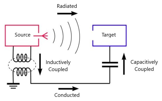
Radiated: this mode of EMI transmission is probably the most obvious.
This is where you have the source and the target separated by a half
wavelength or more and the signal is radiated from the source through the
air to the target.
Conducted: conducted interference is where the signal is
transferred through power lines, cabling or interconnects to the device or
circuit. With this, there are two modes of conduction, Common Mode and
Differential Mode. Common mode is when the noise appears in the same phase
when travelling on the conductors. Differential mode is when they are
out of phase.
Coupled: coupled interference can either be from capacitive coupling and
inductive or magnetic coupling.
Capacitive coupling occurs when a changing voltage from the source capacitively transfers
the charge to the target. Inductive, or magnetic coupling, exists when a varying magnetic field exists between the source and
target, and the signal gets coupled from one to the other.
EMI Measurement - Switching and Linear Power Supplies
More to come ...